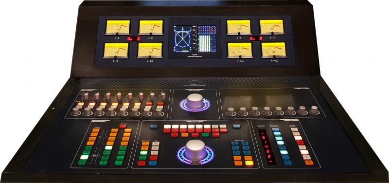
As the first manufacturer worldwide, SPL has developed a stereo and multi-channel mastering console. The goal of the development was a console which is superior in audio quality to all known and foreseeable audio formats, whether analogue or digital, allowing an unrestricted reproduction of the sonic quality of SACD and DVD-Audio and to be a safe capital investment. The MMC 1 operates in the centre of a mastering environment fulfilling the tasks of speaker management, source connectivity, audio metering, track assignment, master and monitor level setting and automated insert routing of external processors.
Fade In ...
Digital audio formats are subject to further development and change. The degree of incompatibility enforced by the format war between PCM and DSD has persuaded us to decide for a technology that is superior in dynamic range, headroom and sound quality and that is discrete analogue technology in its most advanced implementation.
And there are further requirements speaking for the employment of high-performance analogue technology:
The number of necessary AD/DA conversions should be reduced to a minimum. Digital sources can be connected to a digital router (i.e. of Z-Systems), which outputs the selected source through the preferred DA converter to the MMC 1. Thus it is ensured that the sound quality remains comparable and is not affected by converter differences.
From a sound-aesthetical view, high-quality analogue outboard processing is superior to digital processing. The analogue concept allows for problem-free integration of those processors.
Monitors and power amplifiers are mostly analogue designs. Why have another converter in that chain
New Technologies
In the MMC 1 SPL's new SUPRA operation amplifiers are used throughout. They operate at 120 V operating voltage. During a four-year period, SPL has researched this discrete operation amplifier, until the basis of a new generation of analogue audio technology was found. The SUPRA operation amplifier obtains a signal-to-noise ratio of 116dB with an headroom of 34dB. The dynamic range amounts to 150dB with a frequency bandwidth ranging to 200kHz.
With these basic specs, the MMC 1 is beyond the requirements of today's PCM digital formats up to 24 bit and 192kHz sampling rate or DSD digital format with 1 bit and 256 fs.
It is not to be expected that digital technology will offer an environment in foreseeable time, in which the MMC 1 could become a bottle neck.
The MMC 1 configuration in short
In the Source section the Inputs (4x stereo/ 4x 8-channel) and Returns (8x stereo/ 8x 8-channel) can be selected.
The Input section offers a passive router to re-assign the track configurations of the various surround formats to match the SMPTE/ITU standard. Each input channel is equipped with an On, Phase Reverse and a special Trim switch for precise gaining in 0.5dB steps from -9,5dB to +6dB.
The Insert section is quite unique. It offers control functions for an automated patchbay, called Insert Box. Up to eight 8-channel processors can be connected to this outbreak 19" unit. The mastering engineer can store and compare up to four sequences by a push of a button. An all-over bypass switches the Insert Box in and out of processing.
The Monitor section features a central Monitor Level control and switches for Mute and Dim levels. Two stereo loudspeaker sets and two surround loudspeaker sets of up to eight speakers can be connected to the MMC 1.
The speaker management offers an On and a Solo switch for each loudspeaker. The Solo function operates as Solo-in-place. With the Solo-to-Center switch each speaker can be monitored through the centre speaker for better comparison. There is provision to monitor the LFE on the L/C/R. Three Mono functions (L/R; LS/RS; Lt/Rt) and two mode switches for stereo or multi-channel operation round up the Channel Selection section. The meter bridge houses a RTW Surround Monitor 10800x and eight big VU meters with superb ballistics. The remote control for the RTW Surround Monitor is already built into the console next to the calibration switches for the VUs. The VUs can be switched to either show input or output. The VUs can be calibrated to eight different values (0 dB/-2/-4/-6/-8/-10/-12/-14 dB).
The Master section is dominated by a second eight channel level control. With the Master Level control, the overall output level of the desk to the recording sends is governed. The range of adjustment is from -10dB to +10dB.
The Output section offers the same Trim switch for precise gaining as used in the Input section. Level differences, which may have been introduced by outboard processing, can be compensated for each channel in 0.5dB steps ranging from -9.5dB to +6dB.
The sections in detail
Source
The Source section is divided into two departments. On the left side are the selectors for the input sources, which undergo the mastering process. Four stereo sources and four 8-channel sources can be connected to the MMC 1.
On the right side are the selectors for the returns of the recorders, DAW, analogue multi-tracks, SACD- and DVD-Players, TV, AC3/DTS encoder/decoder etc. The Input/Return button switches the monitoring to a total of eight stereo and eight multi-channel returns.
The inputs and the returns can be attached on the back of the MMC 1 both to XLR sockets and to EDAC multi-pin sockets.
Input
The Input section receives the signal selected in the Source section. First the signal goes through a passive routing switch, with which the individual channels can be routed to every other channel. This function is essential regarding the different channel configurations of the surround formats.
A table above the routing switch gives an overview of the most important channel configurations:
DTS: L / R / LS / RS / C / LFE / L(t/o) / R(t/0)
Film: L / LS / C / RS / R / LFE / L(t/o) / R(t/0)
SDDS: L / LC / C / RC / R / LFE / LS / RS
The MMC 1 buss structure for all inputs and outputs follows the SMPTE/ITU track assignment:
SMPTE: L / R / C / LF / E / LS / RS / L(t/o) / R(t/0)
Note: L(t/o) and R(t/0) explained: The appendix t means total and refers to the automatic stereo downmix function within AC3-encoders, whereas the appendix o means only and stands for a separate stereo mix.
The routing selector transfers each conceivable channel configuration into the SMPTE configuration. The high-quality switch has gold-plated silver contacts with a life span of over 25.000 switching cycles.
Audio then runs through an On and a Phase Reverse switch followed by the 32-position Trim switch. The range of trimming is -9.5dB to +6dB in 0.5dB steps. The specialty of this switch is its mechanical architecture that interconnects only two contacts. Common switches route the audio through a chain of resistors switched in series. Thermal noise and tolerances are adding up. The MMC 1 Trim switch avoids that by routing the audio through only one 0,1% metal film resistor at any position.
Insert
While it is relatively easy in a stereo environment to connect processors via a patchbay and specify their sequence, it becomes complicated and time consuming when dealing with surround.
The MMC 1 features an Insert-Box to which up to eight 8-channel processors can be connected. The unique advantage of MMC 1 is that the engineer can specify up to four routings, called sequences, which can be stored and re-called.
The Insert section provides a switch for each of the eight external processors. Depressing them in a sequence specifies the signal flow through the processors. Beside each switch is a seven segment LED-display indicating the current position of the processor in the sequence.
The mastering engineer can use this feature to compare between sequences in a varying order or to compare the same type of processor like equalisers of manufacturer A with manufacturer B.
Three memory banks are available. Together with the current sequence, four different signal flows can be compared instantly. A bypass switches the Insert Box to hard-bypass.
Monitor
The audio signals returning from the Insert Box are sent to the Monitor section and coevally to the recording outputs. The Monitor section is divided in the following sub sections:
Speakers
Two stereo pairs and two surround loudspeaker sets can be connected to the MMC 1 for monitoring.
Channel Selection
Each loudspeaker can be switched on with the On switch, which is labelled with the respective loudspeaker position. Underneath them a Solo function is provided for each loudspeaker. Multiple solo is also possible.
The Solo-to-Center function allows for monitoring of each loudspeaker through the centre speaker to obtain a better comparability. Solo-to-Center can only be activated, if a speaker was switched to solo before. In a multiple solo situation the Solo-to-Center cannot be activated.
The LFE-to-L/C/R switch distributes the LFE signal proportionately on L/C/R.
In the Monitor section two switches are provided to change the MMC 1 configuration from stereo to multi-channel. The stereo switch should be pressed before starting a stereo mastering job to switch off all monitoring functions except for L/R for improved operation safety. When depressing Multi-Channel, the MMC 1 resets itself to the last multi-channel configuration.
The Monitor section offers three mono functions:
1. Mono L/R
2. Mono Rear (cannot be enabled in stereo mode)
3. Mono L(t/o)/R(t/0) (cannot be enabled in stereo mode)
Monitor Level
The Monitor Level is regulated with a genuine custom-made potentiometer with eight chambers. The MMC 1 avoids using DACs, steps ladders or VCAs for this operation. The specifications of this potentiometer are impressive. The maximum tolerance is 0,5 dB over the entire control range! And such a masterpiece deserves an appropriate optical frame: this noble potentiometers is moved with an 60 mm diameter knob of massive aluminium. The scaling is illuminated with 30 blue LEDs on a circular area of 120 mm with a pointer element from miniature orange LEDs.
Dim/Mute/Back
Three Dim levels are available (-10 dB, -20 dB and -30 dB). In addition to the Mute function a switch labelled Back is incorporated. It is used in case a Dim function is activated and afterwards Mute was pressed. The Back function immediately returns to the actual Monitor Level setting without releasing Dim and Mute.
Metering
Right of the Monitor Level potentiometers are the switch functions for the VUs and the RTW Surround Monitor. All functions of the RTW can be controlled remotely. They are placed next to the Monitor Control potentiometer for easy access. Thus the mastering engineer does not need to leave the optimal hearing position.
The VUs are likewise custom-made by a Japanese company, which manufactures VUs with the optimal ballistics. The VUs can be calibrated on eight different reference levels (0 dB/-2/-4/-6/-8/-10/-12/-14 dB). Furthermore the VUs can be switches to indicate either input or output levels.
Master/Output
The MMC 1 provides three eight channel and four dual channel recording outputs. The output section features the same 32-position switch for level trimming in 0,5dB steps as in the input section. Additionally a Master Output level is provided to regulate all eight channels simultaneously. The same potentiometer is used as for the Monitor Level regulation. With this potentiometer, extremely fine recording level settings are achievable to retrieve the very last bit of the recording headroom. Owing to a genuine potentiometer with infinite resolution a dynamic mastering is possible.