Awesome Transistor Amplifier Channel Compressor is a Mono FET Compressor with a Soft Knee. A Line Level Amplifier for True Parallel Compression.
The AwTAC Channel Compressor is a versatile, classic (if not elegant) sounding compressor with simple to use controls designed to stack well in a mix while providing everything from "just a little" to "suck all the air out of the room" amounts of compression. Our approach was to design an old sounding, not overly modern behaving compressor that can sound great on every channel of a console, build up well in a mix and be very quick and easy to get dialed in.
The AwTAC Channel Compressor has a great subtle vibe which wont accidentally do too much, is never too grabby, and can easily be dialed in from fairly transparent operation to completely in your face. It does this effortlessly while maintaining a feels like it's London 1970 attitude.
The AwTAC Channel Compressor is transformer balanced on its input and output for big iron sound and weight.
Every single stage in both the audio and sidechain circuit is comprised of carefully tuned discrete transistor amplifiers.
The AwTAC Channel Compressor features a 10K bridging input that will not load a converter feeding its input.
The AwTAC Channel Compressor attenuates input signal after its input transformer, so it is possible to drive high level to the input for more transformer coloration if desired.
The sidechain uses a FET for its control element, which controls the gain of the input amplifier. The FET is in the sidechain only, the input amp is a bold sounding bipolar transistor amplifier which could work as the line level receiving amplifier in a console.
The FET sidechain does not shunt signal from the input amp, but rather controls the gain of the input amp, so its easy to think of the sidechain as somewhat of an "auto-fader" if such a thing existed. What this makes for is a very very smooth sounding compression circuit that, while FET controlled, tends to feel a bit like an optical type compressor. The circuit maintains all the speed usually associated with FET compressors but has a very, very smooth quality commonly associated with optical compressors.
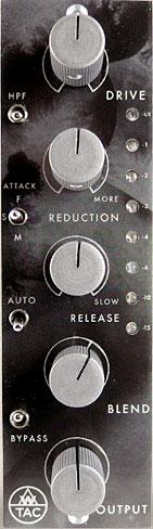
THE METER
The AwTAC Channel Compressor's LED meter is a VERY fast, very accurate peak detecting meter that reads the DC sidechain only. This meter will only ever show the gain reduction in the sidechain, it will never effect the audio path and it is always on. When the Channel Compressor is in bypass mode, the meter will still illuminate if you are feeding signal to the unit.
The AwTAC Channel Compressor has a soft knee compression characteristic. Onset of gain reduction past the threshold is gradual, beginning with a 1:1 ratio and climbing to 10:1 where it remains. Since a lot of useful leveling occurs in this sensitive transition, Displaying good resolution in the first 4 dB of gain reduction was paramount, five out of the available eight segments on the meter display the first 4dB of reduction.
Traditional mechanical GR meters (VU) aren't usually fast enough to detail this sort of activity, which often results in too much compression occurring by the time you really see the meter moving.
Not the case with Channel Compressor where individual LEDs for -0.5dB, -1dB, -2dB, and -3dB show instantaneously the first half of its compression slope.
Four more LEDs, -4dB, -6dB, -10dB, and -15dB then show how the second half of the slope becomes steeper before leveling off at a max gain reduction amount just past the last light.
A very subtle soft knee compression eases in just before the meter lights, taking off a nominal fraction of a dB, the first segment of the meter lights once the compressor is into 0.5 dB of reduction.
The meter is designed to show "subtle compression" to "some compression" to "compression" to "lots of compression". Don't be afraid to light it up, "maximum compression" is off scale.
True Parallel Compression: what your Blend should be.
A Blend control commonly can be a cross fader- what is seen typically on a DJ mixer or on a wet/dry control on a reverb. This can work well in some applications but can be an obstacle when it comes to serious mixing: a cross fader always blends at the same ratio, be it 90:10, 70:30, 50:50, etc. A true parallel circuit and a compression circuit feeding an output summing amp can mix however you'd like, 90:30, 50:10, 60:60, both signal's output level control is completely independent of each other. Adjusting the level of one has no effect on the level of the other.
The theory of operation that you would apply to mixing with parallel compression on a console can be directly applied to using the AwTAC Channel Compressor. This isn't like compressing in parallel. It is compressing in parallel. No tricks. No shortcuts.
Consider how to patch a compressor in parallel with a track on a console in the following example:
Playback feeds channel 14 on the console, and get bussed to the compressor.
The compressor output then gets returned to the console on channel 28.
Now you have two faders on the console: uncompressed playback on channel 14 and the compressor return on 28.
The compressor is working in parallel with the original track that is feeding it. Patched like this, an engineer has full independent control of the level of the uncompressed track on channel 14 and the compressed track on channel 28. This opens up an endless field of creative techniques.
The Output and Blend controls on the AwTAC Channel Compressor work in every way identically to this, they are two independent signals in parallel which combine in a summing amp before the output.
Each Channel Compressor has a dedicated line amp which receives the clean, uncompressed signal from the input, the way that channel 14 in the above example does. The Blend Pot is the fader which feeds that clean line amp. The Channel Compressor Output Pot is the fader that feeds the Makeup Amp, which functions the same way that channel 28 in the above example did.
Similar to the two faders on the console in the example, the AwTAC Channel Compressor's Blend Amp and Makeup Amp both passively sum to the Output Summing Amp. Inside of every Channel Compressor, there is a 2x1 mono summing buss combining the two signals, summing the two signals just like a console would do. Additionally, similar to a fader on a console, the Blend fader has +9dB of gain "in hand" available above unity.
With the AwTAC Channel Compressor you can take your input, set the uncompressed level to your desired level with the Blend Pot (unity gain is 1 O'Clock on the pot denoted by the hash mark on the dial) and then with the Output Pot bring up the compressed signal under it. You can set the compressed level to unity and bring up the parallel blend behind it to air it out. Of course you don't need to use the blend circuit at all, simply rolling the Blend Pot back full counter clockwise will mute the circuit and you'll have a conventional compressor.
The AwTAC Channel Compressor is designed for Stereo use.
Units are stereo linkable following the API standard of merging Pin 6 on your rack for DC linking.
We are very serious about stereo matching at Awtac and there are several parts in the Channel Compressor that are measured, selected and matched entirely by hand. It is labor intensive, but there is no other way to effectively guarantee tight stereo tracking between units:
The sidechain FETs are individually measured by hand, selected and matched in stereo pairs for offset between channels.
One of the problems commonly found in vintage FET compressors when it comes to stereo linking, is one channel reacting a dB off from the other, which pulls the stereo image to one side. Typically, this is caused by offset between the two sidechains. By matching FETs in the sidechain for offset, this problem is minimized.
All the pots on the Channel Compressor are individually measured by hand, selected and matched within 1/10th dB for use in Stereo. The timing capacitors are individually measured by hand, selected and matched so the release tracks as close as possible between left and right units. A stereo pair consists of an odd serial number and the sequentially higher even serial number. IE, 1 & 2, 37 & 38, 145 & 146, etc constitute matched stereo pairs.
Each AwTAC Channel Compressor of course works stand alone in mono.